Measuring the hydraulic gradient using a laser rangefinder
Description
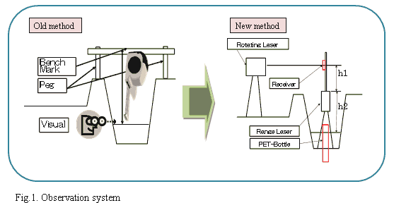
African paddy fields are lined by earth canals which are often vulnerable to natural disasters; hence, appropriate measures based on knowledge of local weather, landform and soil conditions are necessary. To validate the effectiveness of the measures and to evaluate earth canal functions, hydraulic gradients (surface water gradients) have to be measured. In contrast with concrete canal beds, earth canal beds accumulate sediments (soil and sands), making bed level measurements inaccurate. Traditionally, surface water levels are measured directly using metal tapes (Fig. 1); however, this method is difficult for the following reasons:
i) At least two people are needed in order to confirm by visual inspection whether the edge of the metal tape is in contact with the water surface.
ii) An accurate surface water level cannot be measured if the staff does not have good estimation skills, as surface water levels often fluctuate.
iii) Bench marks set on the shoulder of the canal hinder farming activities.
Therefore, a simpler and easier way to measure the hydraulic gradients of earth canals was developed. For this purpose, the laser rangefinder (LR) was found suitable and convenient. Measurements are carried out as follows:
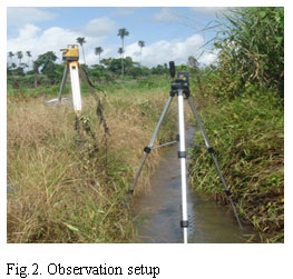
- The hydraulic gradient is easily measured by taking the height (h2) from the water surface at two different points on the canal (Fig. 1, right; Fig.2). Measurement accuracy depends on the resolution of the instrument (resolution of LR is around ±2mm).
- LR is a device that measures distances in a noncontact manner by measuring the phase difference between the laser emitted from the instrument and the laser reflected from the object. Depending on the object, some improvised device may be necessary for the laser to be reflected exactly from the object (surface water in this case) to the LR.
- For this purpose, a tube is made by cutting the top and bottom of a PET bottle after which it is stuck into the earth canal. A float (e.g., a styrofoam board) is placed inside the tube so that the LR can catch the reflected laser light from the water surface.
- Holes or slits are made to the tubes in order to synchronize the water levels inside and outside the tubes. There are two ways to make holes: one is to make a circle (punch a hole); the other is to cut a slit. There are no significant differences in measured data using both methods; however, the ‘punched hole’ method is deemed harder, and consequently, better.
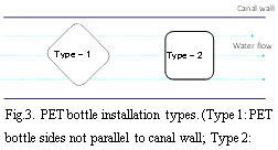
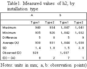
- Measurement accuracy is higher in cases where the cross-section of PET bottles are rectangular.
- The sides of the PET bottle are set parallel to the stream (Type 2) (Table 1, Fig. 3).
The roughness coefficient (i.e., a representative value indicating resistance to flow) of a canal can be calculated by measuring its hydraulic gradient. Not only does it help in developing irrigation plans, but it can also be utilized as an index in evaluating an earth canal’s deterioration. This method can be applied to earth canals of different types, widths, and sizes.
Also, if combined with a rotating laser (the setup consists of an apparatus for generating a level laser beam and the receiving instrument), the relative height (h1) of LR can be measured by oneself (i.e., unassisted). However, the use of rotating lasers is not yet widespread in developing countries. Thus, if local governments or consultants decide to use this method, they will need two or several people and a leveling device to obtain measurements.
Figure, table
- Affiliation
-
Japan International Research Center for Agricultural Sciences Rural Development Division
- Classification
-
Research B
- Research project
- Program name
- Term of research
-
FY 2012 (FY 2011-FY 2015)
- Responsible researcher
-
Hirouchi Shinji ( Rural Development Division )
MIERUKA ID: 001783Dan Haruyuki ( Rural Development Division )
MIERUKA ID: 001800Hirose Chikako ( Rural Development Division )
MIERUKA ID: 001803 - ほか
- Publication, etc.
-
Hirouchi, et al. (2012), Journal of the Japanese Socienty of Irrigation, Drainage and Rural Engineering, 80(9) 715-718.
- Japanese PDF
-
2012_12_A4_ja.pdf40.43 KB
- English PDF
-
2012_12_A4_en.pdf302.43 KB


