Buffered chamber gas measurement apparatus
Description
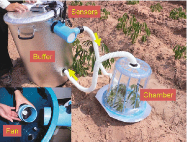
High-performance indoor air quality sensors are now obtainable at reasonable prices and can be used for gas measurement in experimental equipment. Fig. 1 depicts the principles of the method. It essentially involves the closed-chamber method. A closed chamber is divided into a chamber and a buffer zone (buffer). The air is circulated between the chamber and the buffer, and the gas concentration is measured in the buffer. Several problems associated with the chamber method can be solved using this method.
We frequently encounter the problem of condensation while measuring transpiration using the closed-chamber method. Increasing the volume capacity of the buffer can solve this problem. This is because with the improved method, the appearance of condensation can be delayed, allowing the measurements to be completed before it occurs. Obviously, the volume of the buffer must be adjusted to suit the measurement conditions. All the air in the chamber is progressively circulated, and thus fans are not required to prevent irregularities in the chamber. A problem associated with the open chamber method is the effects of irregularities in the outside air. To solve this, a vast buffer room is sometimes used. However, this renders the device less portable and is therefore a disadvantage. Sometimes a reference gas canister is used. This technique gives stable results, but the measurement conditions a are artificial. On the other hand, the use of a closed chamber is limited to suitable objects. The new method increases the range of items that can be measured using a closed chamber.
It is often observed that continuous measurement requires mechanisms by which the lid of the chamber can be repeatedly opened and closed. In the case of our improved method, continuous measurement is easily achieved by ventilating the buffer with a fan.
Calibration of the apparatus is simple to perform. A dish containing water was attached to the load cell and placed in the chamber shown in Fig. 1. The humidity and dew point were measured every minute for 5 min, and the dish was then removed. Measurements were continued for another 2 min. Transpiration and dew point were found to be related (R2 = 0.997). There was little response lag between the buffer and the chamber and at the same time the irregularities in the chamber were minor. It should be mentioned that the volume of the apparatus can be accurately estimated from the calibration line with water vapor, making it possible to calculate the volume of CO2 without using a reference gas.
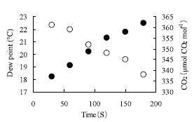
Fig. 2 illustrates an example of the measurement of photosynthesis and transpiration of a tomato plant in the field. The dew point increased by 3.3 ℃, while the CO2 concentration decreased by 24 ppm.
Figure, table
-
Fig. 1. Principle of the buffered chamber method.
Humidity sensor (Extec Ltd., EA-20), CO2 sensor (TESTO Ltd., 535), PC fan and battery, 40-L chamber, 130-L buffer (covered by an insulated sheet), connecting pipes. -
Fig. 2. An example of measurements of photosynthesis and transpiration of a tomato plant in the field.
- Affiliation
-
Japan International Research Center for Agricultural Sciences Crop Production and Environment Division
- Term of research
-
FY2006(FY2006~2010)
- Responsible researcher
-
ODA Masato ( Crop Production and Environment Division )
- ほか
- Publication, etc.
-
ODA, M. (2006): Patent pending.
ODA, M. Buffer Chamber Method for Measuring photosynthesis & perspiration. [Abstract of Spring meeting of the Society of Agricultural Meteorology of Japan 2006], p61
- Japanese PDF
-
2006_seikajouhou_A4_ja_Part10.pdf475.44 KB


